
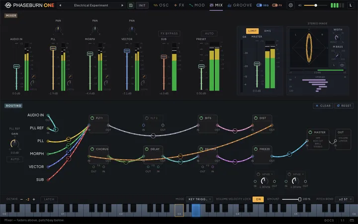
The Mixer tab is where Phaseburn One stops behaving like a fixed-architecture synth. The top of the tab balances the four sources; the rest of it is a patchbay — the routing system every other chapter keeps pointing at, drawn as modules and cables you can rearrange while the sound plays. This chapter explains how the patchbay thinks, how its feedback jacks work without breaking the no-loops rule, and hands over three patches worth stealing.
Faders above, patchbay below
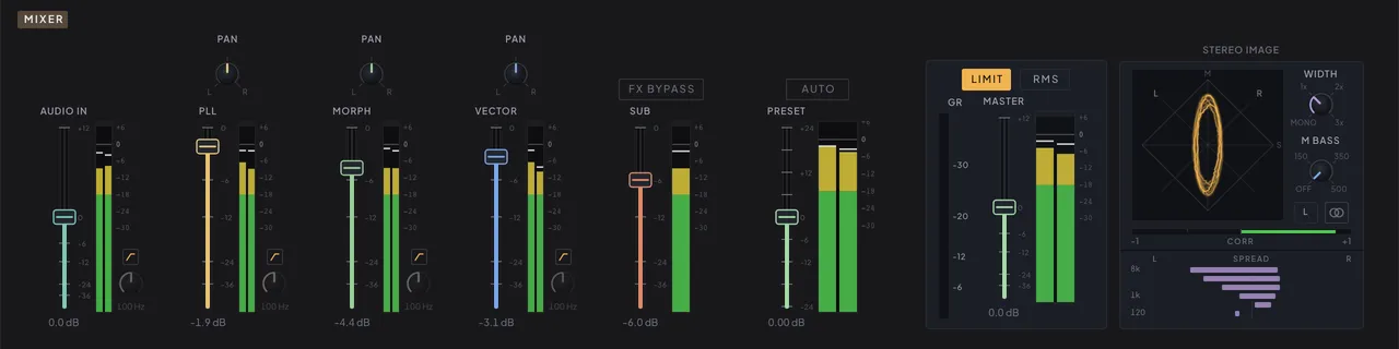
Balance first, rewire second — the Mixer tab is arranged in that order. Across the top runs a row of channel strips: the AUDIO IN input strip, the four sources — the Phase-Locked Loop (PLL) voice, the MORPH and VECTOR oscillators and the sub — then the PRESET fader, and the master at the end. The strips run the full width of the page as console-style faders: a cap riding in a recessed groove, a live stereo level meter beside each, and a proper dB scale up the travel — every mark labelled, 0 at unity down through −6/−12/−24/−36, with the ceiling at the top where a strip has gain past unity. The meters read past full scale — the scale runs to +6 dBFS with a reference line at 0, because the engine’s 64-bit signal path never clips internally: levels above the line fill red and latch the clip lamp at the top of the meter (amber on the source strips, where an over is informational; red on the master, where it is the level your host actually receives), instead of pinning at the top and hiding how hot the signal really is. The source faders are the same volume parameters that end each section of the Oscillators tab, mirrored here for mixing, and they top out at unity — the balance you set is the level every cable from that source starts from. The master fader carries up to +12 dB for the final send to your host. The MASTER strip is the output stage in miniature: the limiter’s gain-reduction meter beside the fader, a LIMIT switch — the same output limiter as the header’s L button, duplicated here so the whole output stage is in one place, and the one switch that decides whether the plug-in reports any latency to your host at all (see The master section (Chapter 6 — Effects & Master)) — and an RMS/PEAK ballistics switch for its meter.
Above the PLL, MORPH and VECTOR faders sits a small PAN knob: a stereo balance with a constant-power law, so a source keeps its perceived weight as it moves off-centre, and bit-transparent at centre — presets saved before the knob existed sound identical. Each pan is a modulation destination in its own right, with a modulation ring on the knob, so an LFO or step lane can swing a source across the field (the modulation chapter (Chapter 4 — Modulation) covers routing). The sub has no pan: it is mono by design, and the low end stays planted in the centre.
At the foot of the AUDIO IN, PLL, MORPH and VECTOR meters sits a cleanup highpass: a switch drawn as a highpass curve, and a corner frequency from 20 to 300 Hz that reads in hertz and can be typed into, dimmed while the switch is off. It is a hard cut — 48 dB per octave, so an octave below the corner is already 48 dB down. That is the point: it clears rumble and low-mid clutter out of one source without touching the next one, where routing a source into the main filter to do the same job would spend the whole filter section on it and drag everything else routed there along. Set the corner just under the lowest note that source has to keep.
Each highpass is off by default, at 100 Hz, and saves with the preset — nothing saved before they existed changes. They are deliberately not modulation destinations: where a source sits in the low end is a mixing decision, not something to sweep. Nor do they change what the PLL locks onto. A source patched into PLL REF, and AUDIO IN itself, still hand the comparator their full range, so a reference can go on being a bass line however the strip is filtered.
The PRESET fader, just left of the MASTER strip, is a per-preset volume offset of ±24 dB saved with each patch, there to level-match presets against one another; the master fader itself stays a global performance control, and loading a preset never moves it. Set it by ear, or let the instrument do it: press AUTO above the fader and it levels the patch for you.
AUTO matches loudness, not peaks. Two patches can share a peak level and still sound nothing like the same volume — a sparse percussive patch and a dense saturated one differ by more than 10 dB in how loud they read at the same peak, which is why peak-matching leaves a bank feeling uneven. So AUTO measures loudness the way broadcast and streaming do, and sets the offset to put this patch on the same footing as every other one. It will not push a patch’s peaks past −1 dBFS to get there: a patch with very sharp transients lands a little under, rather than being levelled into the limiter.
It works from what it has just heard. The instrument keeps a few seconds of rolling measurement while the mixer is open, so pressing AUTO while a patch is playing normally answers straight away. Press it right after loading a preset and there is nothing measured yet — the button fills as it listens, and sets the fader once it has heard enough. Loading a preset clears that measurement, so AUTO never levels one patch using another’s audio.
The reading is taken from an engine tap just before this fader, after the master tone chain but before the preset offset, the master fader and the limiter. That makes the calibration absolute: the master fader’s position never skews it, pressing AUTO twice changes nothing the second time, and a patch with nothing audible reports NO SIG instead of guessing.
The meter beside that fader reads the preset stage — the mix with this offset applied and nothing after it. The master fader does not move it, which is the point: it reports the level this strip is responsible for handing on. The MASTER strip’s own meter, at the end of the chain, is where you read what actually leaves the instrument.
The effects have no strips here — their levels live where the effects do. Each module’s MIX knob on the FX tab sets its dry/wet blend, the distortion adds a LEVEL knob for output level on the processed signal, and the gain of the cable an effect returns into the master — set in the patchbay below — decides how loud that effect lands in the sum. The cables are the effects’ faders.
Below the faders is the patchbay: every routing decision in the instrument, drawn as boxes and cables. The oscillators, the two filters, the six effects and the master appear as modules; the lines between them are cables, and dragging a cable is rewiring the instrument. By default the modules sit in two rows — the core chain (FLT 1, FLT 2, BitCrusher, distortion) on top and the time-and-space effects (chorus, delay, reverb, freezer) below, with the oscillator sources anchoring the left edge and the master and output the right. Modules can themselves be dragged anywhere on the canvas to keep a busy patch readable — the layout is cosmetic, the cables are the signal path.
Nothing here needs to be patched before the instrument makes sound. A fresh preset arrives with the backbone already wired: the four sources → FILTER 1 → FILTER 2 → BitCrusher → distortion → chorus → delay → reverb → freezer → master, every cable at unity gain — passing signal at exactly the level it receives — with both filters and every effect powered off. A powered-off module passes its input straight through, so the default patch is a transparent wire from the oscillators to the output; the chain only starts sounding like a chain when power buttons come on (the effects chapter (Chapter 6 — Effects & Master) walks through each module). The patchbay is not setup work — it is where you go when the stock order stops being the arrangement the music wants.
Phaseburn One runs one voice by design, and this tab is one of the places that budget shows: there is exactly one of every module — one distortion, one delay, one reverb — each running full-depth processing on the single voice, with the cables deciding where in the story each one sits.
The stereo meter
To the right of the MASTER strip sits the stereo meter — the output stage’s eyes. It listens to the same signal the master meter does, after the limiter, exactly what your host receives, and answers three questions at a glance: what shape is the stereo image, will it survive a mono fold-down, and where in the spectrum the width actually lives.
The square display is a goniometer, drawn the way hardware draws it: mono material traces a vertical line up the middle (the M axis), a source that exists only in the left channel leans onto the L diagonal, and the wider and less correlated the signal gets, the rounder the amber figure blooms. Anything stretching horizontal is anti-phase energy — the part a mono playback system cancels. The beam persists for a moment like a phosphor trace, and the display gently rescales quiet passages so the figure stays readable instead of collapsing into a dot at low level.
Beside the goniometer sit the instrument’s stereo controls, so the image is adjusted right where it is measured. WIDTH and M BASS are the master chain’s stereo-control stage, placed here beside the display that judges them: width scales the whole image from mono up to three times its recorded spread, and the mono-bass crossover sums everything below its frequency — up to 500 Hz — to the centre. Under them, MONO is a monitor check, not a parameter: it folds the output to the mono sum so you can hear exactly what a single-speaker system receives while the meters show it — the figure collapses to the M axis and the correlation bar pins to +1. It is click-free, never saved with anything, and always off when the editor reopens, so a forgotten mono check can’t follow a project home.
Under it, CORR is the classic phase-correlation meter, integrated over a few hundred milliseconds so it reads as a tendency rather than a flicker: +1 means the channels agree (perfectly mono-compatible), values around 0 mean wide, decorrelated material, and negative readings fill red toward −1 — real phase cancellation that will lose level in mono. A red tick holds the deepest negative excursion for a couple of seconds, so a brief polarity problem is caught even when you look up late.
SPREAD breaks the same question across the spectrum: six bands from the sub region to the air (split at 120, 350, 1k, 3k and 8k Hz), lowest at the bottom, each drawn as a horizontal bar whose position is the band’s left/right balance and whose length is its width. A healthy mix for club playback shows exactly the ladder you would hope for — a centred dot or a stub in the bottom rows where the bass stays mono, bars widening toward the top where the chorus and reverb live. A band with no energy collapses to a small dot at its balance position, so the ladder keeps its shape even in sparse material.
The meter needs no switch: it is always on, and the analysis runs only while the Mixer tab is actually visible, so it costs nothing the rest of the time.
How the patchbay thinks
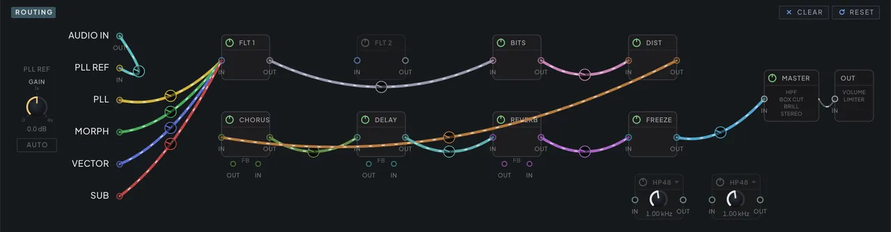
Route anything anywhere and the result stays predictable, because the whole system obeys three rules you can hold in your head: inputs sum, outputs fan out, loops are refused.
The pieces. Every box is a node with ports. The four oscillators and AUDIO IN have outputs — AUDIO IN’s jack is captioned OUT, because the audio arriving from your host leaves here for the rest of the panel; the two filters and the six effects each have an input and an output; the master and PLL REF have only an input. A cable connects one output to one input, and every cable carries its own gain: silence at the bottom of its travel, unity most of the way up, and up to +6 dB of push at the very top — enough to drive a return hot straight from the patchbay. Drag vertically on a cable’s knob to set it, hold Shift for fine moves, and the help bar along the bottom reads the level out live in dB; a cable pushed toward the top shows an amber halo as a near-clip warning. The knob bottoms out at silence with the cable still patched — a lane held open, ready to fade back in — and removing a cable is a click on the cable itself. Cables also show their traffic: one carrying live signal streams a faint run of dashes from its source toward its destination, glowing brighter the more signal it carries, so a patched-but-silent cable sits still while the working path shimmers. Brush the pointer across a cable and it sways once, like a nudged patch lead, then settles. The filters’ cables carry gain like everything else: the per-source direct lines — the sub’s included — and the effect returns into either filter all scale their signal continuously. Presets from earlier builds, where these read as plain on/off, load at exactly off or unity — the old sound, untouched.
Inputs sum. Several cables can land on one input and their signals are mixed — all the oscillators into FILTER 1, each at its own level, or the filter and the delay together into the reverb.
Outputs fan out. One output can feed any number of destinations at once, each through its own cable at its own level — the filter into the chorus, the delay and the master simultaneously.
The filter is a node like any other. FILTER 1’s input takes cables from every effect output and from the feedback taps, so the classic orders that used to be impossible are one drag away: distortion into filter, a delay tail through a resonant sweep, a reverb feedback loop squeezed through the ladder. While nothing external feeds it, the filter keeps its place in the voice exactly as before; patch an effect into it and it steps out onto the bus — the voice’s envelope then shapes only the oscillators’ share of its input, and effect tails keep flowing through the filter after the note ends. The filter’s output can also return into any of the feedback inserts — the dub classic of a delay’s feedback path squeezed through a resonant sweep is a tap, a return and a cutoff knob away.
Two filters, any arrangement. FILTER 2 is a second, complete filter with the same inputs and outputs as the first, and it follows every rule above. The two boxes — FLT 1 and FLT 2 — sit side by side at the head of the top row by default. Cable FILTER 1 into FILTER 2 for a series pair (the default patch already does), give each its own oscillators and send both onward for a parallel pair, or park FILTER 2 after an effect entirely. Either filter can feed the other, but not both ways at once — that would be a loop. Switch FILTER 2 on with nothing patched into it and its box turns yellow and offers a PATCH suggestion, like every other module that has power but no signal.
Loops are refused. The patchbay only offers connections that keep signal flowing one way; a cable that would close a circle cannot be drawn, and the engine enforces the same rule underneath. The only feedback anywhere is each effect’s own internal loop — plus the explicit feedback jacks in the next section.
Cables carry the whole signal. Every effect is a true insert: its output cable carries the effect’s complete result — the input it received blended with the processed signal according to its MIX control — not a wet-only tap. Chaining delay into reverb therefore sounds like a delay feeding a reverb, and a fanned-out output gives every destination the same full signal. Which blend law each MIX uses varies by effect and is covered in the effects chapter (Chapter 6 — Effects & Master).
Power off means wire. Switching an effect off turns it into a clean pass-through while its tail rings out naturally — signal routed through an off module always keeps flowing.
Power on without cables warns. The opposite state — a module switched on with no cable into its input or none leaving its output — is a dead end: the module runs, but its sound never reaches the master. The two HP/LP boxes are the deliberate exception and never turn yellow: they are bare insert filters with no voice of their own, so an uncabled one is idle rather than a dead end. Everywhere else the patchbay flags it in yellow, on the module’s outline and its power ring, until both jacks carry a cable; the module’s power button on the FX tab turns yellow too and reads PATCH. Switching a module on from that tab while it is unwired also opens a prompt that can fix it for you: one click splices the module into the current chain at its most natural point — re-routing the cable it replaces so no dry shortcut dilutes the effect — or jump straight here with the module pulsing and wire it by hand.
The master is a sum, not a default. Nothing reaches the output without a cable into the MASTER box, whose jack reads MASTER EQ; a fixed wire then carries its sum on to the OUT node. Across the two, one fixed chain runs — high-pass, box cut, brilliance and the three EQ bands in MASTER EQ, then stereo control, then volume and the limiter in OUT — described in the master section (Chapter 6 — Effects & Master). The MASTER box carries a power button in its header, the same switch as the Master EQ panel’s on the FX tab. It is always fed, so it never turns yellow and never asks to be patched.
A filter pick stands alone. An effect fed from a filter’s output takes that source exclusively — patching FILTER 1 into it releases the PLL, MORPH and VECTOR sends on that effect, and patching one of those oscillators releases the filter cable in turn. FILTER 2 follows the same grammar on its own jacks. The per-oscillator sends are the loose end: several oscillators can feed the same effect side by side, summing at its input. What sits outside the rule entirely, and so survives any filter pick, is everything that is meant to sum: the sub’s direct sends, AUDIO IN, the HP/LP outputs, the master and PLL REF lanes and the feedback returns. Cables between effects, and the feedback pairs, stack freely.
HP/LP: two filters that live in the bay
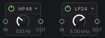
Two more filters sit in the patchbay and nowhere else. HP/LP 1 and HP/LP 2 are plain insert filters — no envelope, no drive, no panel on the FX tab — and they exist for the jobs the voice filters are too characterful for: clearing the mud under a reverb return, taking the fizz off a feedback loop, narrowing a source to a band before it meets a distortion.
Both boxes are always on the canvas, on the free space under the MASTER box, and both arrive switched off at HP48, 1 kHz with nothing cabled — so nothing about an existing patch, preset or session changes until you power one up and wire it.
The box title is the mode. It reads the response the filter is in, with a caret beside it, and clicking it opens the six choices:
| Mode | What it does |
|---|---|
| LP24 · LP48 | lowpass at 24 or 48 dB per octave |
| HP24 · HP48 | highpass at 24 or 48 dB per octave |
| BP12 · BP24 | bandpass at 12 or 24 dB per octave, peaking at unity |
One Frequency knob per box covers 20 Hz–20 kHz in every mode. The title is also the box’s grab handle: click it for the menu, press and drag it to move the box, exactly like any other module.
Wiring is unremarkable by design, which is the point — each slot takes AUDIO IN, all four oscillators, both filters, every effect output and the three feedback taps, and its own output reaches the filters, every effect, the three feedback returns, the master sum, the freezer and PLL REF. The two slots can also feed each other, so the pair chains in series for a 96 dB slope or a band with independent edges; only one direction at a time, since the other way would close a loop.
Changing mode while audio is running is safe: the incoming response is warmed up and crossfaded in over about 20 ms, so a mode switch — by hand or under automation — neither pops nor thumps. The power switch behaves like every other module’s: off is a bit-exact wire, faded rather than cut.
| Parameter | Range | Default | What it does |
|---|---|---|---|
| HP/LP 1 Enable | Off / On | Off | Switches HP/LP 1 on or off; off — which is how it ships — it passes its input through untouched. |
| HP/LP 1 Mode | LP24 · LP48 · HP24 · HP48 · BP12 · BP24 | HP48 | Picks the response — two lowpass, two highpass and two bandpass slopes (LP24/LP48/HP24/HP48/BP12/BP24), the number giving the dB per octave. Starts at HP48. |
| HP/LP 1 Frequency | 20 Hz – 20000 Hz | 1000 Hz | Corner frequency for HP/LP 1 — cutoff for the low/high-pass modes, center for the two bandpass modes. |
| HP/LP 2 Enable | Off / On | Off | Switches HP/LP 2 on or off; off — which is how it ships — it passes its input through untouched. |
| HP/LP 2 Mode | LP24 · LP48 · HP24 · HP48 · BP12 · BP24 | HP48 | Picks the response — two lowpass, two highpass and two bandpass slopes (LP24/LP48/HP24/HP48/BP12/BP24), the number giving the dB per octave. Starts at HP48. |
| HP/LP 2 Frequency | 20 Hz – 20000 Hz | 1000 Hz | Corner frequency for HP/LP 2 — cutoff for the low/high-pass modes, center for the two bandpass modes. |
Audio from outside
Phaseburn has a stereo audio input, and it appears in the patchbay as a source: AUDIO IN, alongside the four oscillators. There are two ways to feed it, and they sum, so whichever your host makes easy is the right one:
- Insert Phaseburn on an audio track. The track’s signal arrives on the main input.
- Send to it from another track. Phaseburn also exposes a stereo sidechain, which is what you want when it is sitting on an instrument track playing notes.
Two host-specific notes. In Logic’s instrument slot (the AU), there is no track input and the sidechain bus is not offered either — instead, Logic’s channel strip has a Side Chain menu in the plug-in header. Pick any track or bus there and it arrives on AUDIO IN like everywhere else; everything below works the same.
In Studio One / Fender Studio Pro, a plug-in is filed as either an instrument or an effect, and sidechains are offered to effects only — so use the VST3, which declares itself as both. It is listed under Effects as well as Instruments there; drag it from the Effects list onto an audio track and the track arrives on AUDIO IN. The CLAP and the AU are instrument-only in that host and cannot receive audio.
Two things follow from that.
The effects work on outside audio. Patch AUDIO IN into the filter, the granular freezer, the BitCrusher — any of them — and on to Master. The effects chain runs whether or not a note is held, so this needs no key press and no sequencer: Phaseburn becomes a processor. The freezer in particular has only ever been able to hear Phaseburn’s own oscillators, and now it can hear anything.
The PLL can lock to it. The PLL REF jack, second from the top of the source column directly under AUDIO IN, feeds the phase-locked loop’s reference. Patch AUDIO IN into it, turn up the PLL’s INPUT REF knob, and the oscillator starts chasing the incoming signal — and falls quiet when that signal stops, so a track that pauses leaves silence rather than a drone. See Locking the loop to something else (Chapter 2 — Oscillators) — that is where the musical part lives.
PLL REF accepts every output on the panel, not only AUDIO IN: the four oscillators, both filters, every effect, and the three feedback taps. Patching an oscillator is cross-modulation inside the instrument with no host routing at all; patching an effect return locks the loop to something that has already been through the chain. Sources downstream of the voice arrive one buffer late — see Locking the loop to something else (Chapter 2 — Oscillators) for what that costs.
Set the reference level. Because any output can be the reference, the calibration belongs to the destination rather than to any one source: the ROUTING panel carries a PLL REF column at its left with a GAIN trim on the summed reference bus and an AUTO button beside it. Feed the loop whatever you are locking it to, press AUTO, and it listens for two seconds and sets the trim so the summed reference peaks at −6 dBFS. That matters more here than anywhere else on the panel: the phase comparator only registers an edge once the reference crosses ±0.02, about −34 dBFS, so a reference that is merely audible may still never lock. −6 dBFS leaves about 28 dB of margin over that while staying clear of the level where the loop’s own soft bound would start reshaping the waveform. The meter and AUTO read the bus itself, not the blend — they work with the PLL’s INPUT REF knob anywhere, even fully at INT, so you can calibrate the trim first and only then open the blend onto a correctly levelled reference.
GAIN is unity by default and applies to everything patched into PLL REF at once, external and internal alike. The AUDIO IN strip’s fader is still the input trim for the rest of the instrument — it is what the filters and the effects receive.
Nothing here is on until you patch it. With no cable from AUDIO IN the input is inert and the instrument behaves exactly as it did before — an insert with nothing patched passes no audio through, because the plugin still owns its own output.
Feedback without forbidden loops
Put one effect inside another effect’s feedback loop — a distortion that dirties every repeat of a delay, a chorus that re-blurs each pass — without ever breaking the no-loops rule. That is what the FB jacks are for.
The delay, the chorus and the reverb each carry a pair of extra jacks on their bottom edge: a feedback tap, which emits what is circulating inside that effect’s loop, and a return, which accepts signal back into the loop. Patch the tap through another module and into the return, and the loop now runs through your insert — every pass of the feedback is processed again on its way around. For the delay and the chorus, the moment anything lands on the return the effect hands its loop to the external path — so a return patched without its tap feeding the insert starves the loop. The reverb is gentler: its return adds into the tank while the reverb’s own decay keeps running, so it behaves as an injection port rather than a replacement. Pull every return cable back to zero and the internal behavior is restored exactly.
Here is why this is not a forbidden circle. The tap plays what the loop recorded on its previous pass; the return records what will circulate on the next one. The inserted effect sits between passes of the loop rather than inside a closed circle of the outer graph, so signal through the patchbay still flows strictly one way. However hard a loop is pushed, the routing graph can never stall the audio — signal always keeps flowing to the output. What stays your responsibility is level: the inserted effect runs whole inside the loop, including any feedback of its own, and no limiter guards the loop internally. Insert the chorus into the delay’s loop with both feedbacks pushed high and the nested loop can still run away — when a loop starts climbing, back one of the two feedbacks off.
Each of the three loops accepts an insert, and the choice is wide: the distortion, the BitCrusher, the freezer, either filter, either HP/LP slot, or one of the other time effects — every pairing wired as its own tap-and-return pair. A tap also fans out like any other output, so you can listen to a loop without inserting into it: send the delay’s tap through the distortion and onward into the reverb, and everything circulating in the loop — the first echo included — blooms into space, while the dry note passing through the delay stays out of that lane.
Three patches worth stealing
Three routings that earn their cables. Each one starts from the default patch, takes under a minute to wire, and produces something the stock chain cannot.
A distortion inside the delay’s feedback. Power on the delay and the distortion, and
raise the delay’s feedback further than good taste normally allows. In the patchbay, patch
the delay’s FB tap into the distortion and the distortion back into the FB return
(delay_fb_to_comp and comp_to_delay_fb — cable ids that predate the module and were kept
so old patches keep working). Every repeat now passes through the drive before re-entering
the loop, so the echo does not simply fade: it degrades, each pass grittier and more
compressed than the last, until the tail is pure texture. Start with OD and a low DRIVE — the
cascade squares off fast once it is fed its own output, and a loop already past unity does
not need much help. LOW to the right keeps the sub clean so the low end does not turn to
mud as the tail thickens, and TONE pulled down stops the repeats from getting brighter each
pass, which is what runs a feedback loop away. Nothing here limits the loop, so if a swell
keeps climbing, pull the delay’s feedback back down first. There is one distortion in the
instrument, so while it lives in this loop it does this job everywhere it is patched.
Its controls (Chapter 6 — Effects & Master) move with it —
only its address changed.
A BitCrusher parallel to the dry signal. In the default chain the BitCrusher sits in series, so powering it on damages everything downstream. For weight without total destruction, move it beside the chain instead of inside it. Unpatch BitCrusher → distortion, patch FILTER 2’s output into the distortion to close the clean backbone again, then give the BitCrusher a new cable straight to the master and power it on. FILTER 2’s output now fans out into two lanes: the untouched chain, and a crushed lane that meets it again at the master sum. Set the BitCrusher’s MIX fully wet so the parallel lane is pure grit, then balance the blend with the gain knob on the BitCrusher → master cable — that one knob is the clean/destroyed balance. BITS and FREQ (Chapter 6 — Effects & Master) choose the flavor of damage.
The sub straight to the output. Build a bass patch that gets filthy — filter drive, coloration, the crushed lane above — and the low end usually gets filthy with it. Flip the sub’s FX BYPASS switch — on the SUB section header of the Oscillators tab, or on the mixer’s SUB strip right above the patchbay — and the sub steps out of the graph entirely: its normal cables dim, a single loose-hanging cable appears from the sub to the OUT block — the final volume-and-limiter stage, drawn past the master — and the raw sub, still shaped by its volume, envelope and velocity, is summed in after the master tone stages, ahead of only the master volume and the limiter. The fundamental now ignores the filter sweep, the distortion, even the master high-pass: chaos on top, a clean floor underneath. Clicking that cable (or the switch — they mirror each other) puts the sub back into the graph. For a milder split that keeps the master tone stages in play, use the sub’s master-direct cable instead: it adds the raw sub into the master sum ahead of the tone chain. The sub’s section (Chapter 2 — Oscillators) covers its shape and saturation controls.
Every cable is a parameter
Automate the wiring itself. Every cable in the patchbay is a plug-in parameter, visible to
your host like any knob, and the cables of the effects graph — sends, links between
effects, feedback pairs, master lanes — are continuous levels, not on/off switches. Draw a
slow ramp on a reverb send and the space fades in across a phrase; snap a delay send
between zero and unity per section and the arrangement gains an effects lane the instrument
performs by itself. Cable moves are smoothed inside the engine, so automated patching
connects and disconnects without clicks. At the parameter level an exact zero still means
disconnected — automation that writes 0 unpatches the cable; the knob’s on-screen floor
stops just above it, keeping the lane patched. The cables into the filters have the
same real travel as every other lane — ramp filter_in_pll and the PLL fades out of
FILTER 1 while the rest of its input plays on. One quiet
consequence: the
FILTER 1 exclusivity from earlier is patchbay courtesy, not engine law — automation
is free to raise several source sends into the same effect at once, and the graph sums
them.
The cable families, compactly:
- Front end. Each source into FILTER 1 —
filter_in_pll,filter_in_vps,filter_in_saw, andsynth_sub_filter_routefor the sub — and the same four into FILTER 2 (filter2_in_plland its siblings), plus AUDIO IN into either (in_to_filter,in_to_filter2) and the two filters into each other (flt_to_filter2,flt2_to_filter). - Sends. Every effect’s inputs: one cable from each oscillator — the sub included
(
sub_to_delayand its siblings; the sub’s sends sit out while SUB DIRECT is engaged, keeping that path clean) — and one from each filter’s output (chorus_send_pll,bitcrusher_send_flt_out,delay_send_flt2, …). The reverb adds a send from the delay, the cable that closes the default chain. - Between effects. A cable from every effect’s output to every other effect’s input, in
both directions (
comp_to_reverb,rvb_to_chorus,delay_to_bitcrusher, …) — chains in any one-way order, or parallel banks that meet at the master. Both filters join that mesh: every effect output and every feedback tap can land on either filter’s input (comp_to_filter,delay_fb_to_filter2, …), and either filter’s output can return into any feedback insert (flt_to_delay_fb,flt2_to_rvb_fb, …). Plus the feedback tap and return pairs from the previous section (delay_fb_to_comp,comp_to_delay_fb, …). - The HP/LP slots. Sixty more cables, thirty per slot, wired the same way: everything
that can drive a filter can drive an HP/LP (
in_to_hplp1,rvb_to_hplp2,delay_fb_to_hplp1, …), and its output reaches the filters, every effect, the three feedback returns, the master, the freezer and PLL REF (hplp1_to_filter2,hplp2_to_chorus_fb,hplp1_to_master, …) — plus the cross pair (hplp1_to_hplp2,hplp2_to_hplp1) that chains the two. - Into the master. One cable per effect (
reverb_to_master, …), each filter directly (flt_to_master,flt2_to_master), and raw oscillator lanes (master_direct_pllthroughmaster_direct_sub) that skip the processing chain and add straight into the output sum.
The complete listing — every cable with its range and default — lives in the full parameter index (Chapter 12 — Reference), most of it under the routing module; the sub’s filter line is listed with the sub’s own parameters, and SUB DIRECT with the master section. The routing module also carries the four oscillator-independence switches; those belong to the skip-and-drift story in the oscillators chapter (Chapter 2 — Oscillators).
Everything survives the session. Every cable — backbone, parallel lanes, feedback inserts — is saved with the preset, and so are the module positions on the canvas; positions persist with the DAW project too, so a patch reopens looking the way you left it. Presets from earlier builds that stored connections as plain on/off load those cables at off or unity.
One thing automation can reach that the panel never offers: both halves of a pair that would close a loop. The panel refuses the second cable, but an automation lane, a mapped CC or a hand-edited preset file can set both — and then the engine drops one of them. The dropped cable draws dimmed, and hovering it names the cable it would have looped with, so a lane that is not being heard says so rather than looking live.
And when a patch has drifted past understanding, two header buttons put it right. CLEAR unpatches: every cable and the SUB DIRECT lead go to silence, and nothing else moves — every module stays exactly where it is, HP/LP boxes and their settings included. RESET restores the default patch: the default cables, every module back at its default spot, and both HP/LP boxes back to off at HP48, 1 kHz. Neither button touches the effects’ power switches — power is separate from patching. Double-clicking the empty canvas tidies only the layout and leaves the wiring alone.